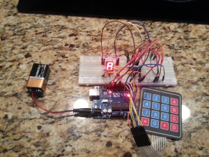
Arduino Experiment #1 – 4×4 Keypad, 7 Segment Display and 74HC595 IC
Description
After looking for different tutorials on how to use the 4×4 keypad on the Sunfounder website and getting bits and pieces, I decided to publish my findings because a) I forget and b) maybe someone else will find this useful. This arduino experiment is based on a few different tutorials I’ve found on the Internet.
- http://tronixstuff.com/2013/12/16/arduino-tutorials-chapter-42-numeric-keypads/
- http://www.sunfounder.com/index.php?c=case_in&a=detail_&id=23&name=Arduino
- http://www.sunfounder.com/index.php?c=case_in&a=detail_&id=145&name=Arduino
Using the shiftOut function to write to the 74HC595, the 7 segment display LEDs have corresponding values when controlled through the 74HC595. ( See the crude ascii art comments below the keymap array below.) I then added the appropriate values for the 4th column to the keymap array. From there, its a matter of mapping the key value returned from customKeypad.getKey() to the values in the keymap array.
I had trouble reading from PIN 1 on the arduino, so I switched to PIN 9. I’m new to hobby, so I am not sure if there is a way to switch PIN 1 to an input.
One thing they don’t mention is that you have to download and install the Keyboard library found at http://playground.arduino.cc/Code/Keypad#Download
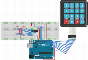
Breadboard View
Code
//
//4x4 Keypad, 7 Segment Display and 74HC595 IC Experiment #1
//
#include <Keypad.h>

const int latchPin = 12; //Pin connected to ST_CP of 74HC595 - time sequence input of memory
                         //register. On the rising edge, the data in shift register moves
                         //into memory register
const int clockPin = 8; //Pin connected to SH_CP of 74HC595 - time sequence input of
                        //shift register. On the rising edge,
                       //the data in shift register moves successively one bit, i.e.
                       //Data in Q1 moves to Q2, and so forth.
                       //While on the falling edge, the data in shift register remain unchanged

const int dataPin = 11; //Pin connected to DS of 74HC595 - Serial data input pin

//display           0,  1,   2,   3,   4,   5,   6,   7,   8,   9,   A,  b,   C,   d,   E,   F
int keymap[16] = {252, 96, 218, 242, 102, 182, 190, 224, 254, 246, 238, 62, 156, 122, 158, 142};

//   ___ 128
// 4 | |  64
// 2 ---
// 8 | |  32
//16 ---  *1

const byte ROWS = 4;
const byte COLS = 4;
char hexaKeys[ROWS][COLS] = {
  {'1','2','3','A'},
  {'4','5','6','B'},
  {'7','8','9','C'},
  {'*','0','#','D'}
};

byte rowPins[ROWS] = {0, 9, 2, 3};
byte colPins[COLS] = {4, 5, 6, 7};

Keypad customKeypad = Keypad( makeKeymap(hexaKeys), rowPins, colPins, ROWS, COLS);

void setup ()
{
  //set pins to output
  pinMode(latchPin,OUTPUT);
  pinMode(clockPin,OUTPUT);
  pinMode(dataPin,OUTPUT);

  Serial.begin(9600);
  displayKey('0');
}
void loop()
{
  readKey();
}

void readKey(){
  char key = customKeypad.getKey();
  if (key != NO_KEY)
  {
    displayKey(key);
  }
}

void displayKey(char key){
  Serial.write(key);
  int keycode = 0;
  switch(key){
    case '0':
      keycode = keymap[0];
      break;
    case '1':
      keycode = keymap[1];
      break;
    case '2':
      keycode = keymap[2];
      break;
    case '3':
      keycode = keymap[3];
      break;
    case '4':
      keycode = keymap[4];
      break;
    case '5':
      keycode = keymap[5];
      break;
    case '6':
      keycode = keymap[6];
      break;
    case '7':
      keycode = keymap[7];
      break;
    case '8':
      keycode = keymap[8];
      break;
    case '9':
      keycode = keymap[9];
      break;
    case 'A':
      keycode = keymap[10];
      break;
    case 'B':
      keycode = keymap[11];
      break;
    case 'C':
      keycode = keymap[12];
      break;
    case 'D':
      keycode = keymap[13];
      break;
    case '*':
      keycode = keymap[14];
      break;
    case '#':
      keycode = keymap[15];
      break;
    default:
      keycode = 0;
      break;
  }
  digitalWrite(latchPin,LOW); //ground latchPin and hold low for as long as you are transmitting
  shiftOut(dataPin,clockPin,MSBFIRST,keycode);
  //return the latch pin high to signal chip that it
  //no longer needs to listen for information
  digitalWrite(latchPin,HIGH); //pull the latchPin to save the data
}

